Updated 3/8/08
AUTOSLOT Do It Yourself Kit
Features of the AUTOSLOT Do It Yourself Kit
All settings adjustable by using the 3 existing reel stop buttons on your machine.
You can select Auto Stop mode ON or OFF.
The order in which the reels stop is selectable between traditional left to right order, or random order.
You can control both how long until the reels begin to stop and how much time between each reel stop.
All settings are retained after machine is turned off! No need to select each setting every time the slot machine is powered up.
Credit Add function. (See PachiTalk page.)
Differences between the AUTOSLOT Do It Yourself Kit (DIY) and the AUTOSLOT Cable
DIY Kit requires modifying your stop board, including soldering.
DIY cannot be used on machines with greater than 5 volts on spin lever.*
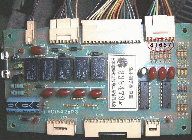
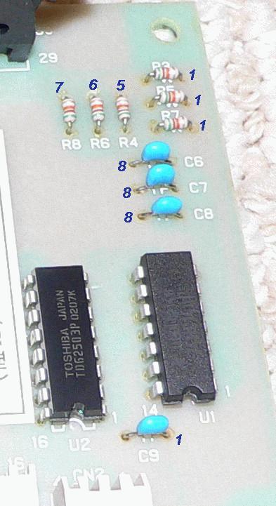
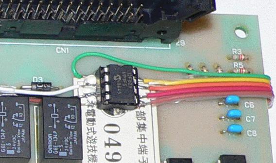
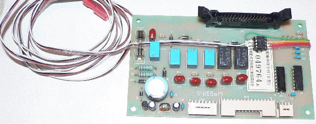
The pictures below show locations of where to solder wires to. You can choose to solder on either side of the stop board.
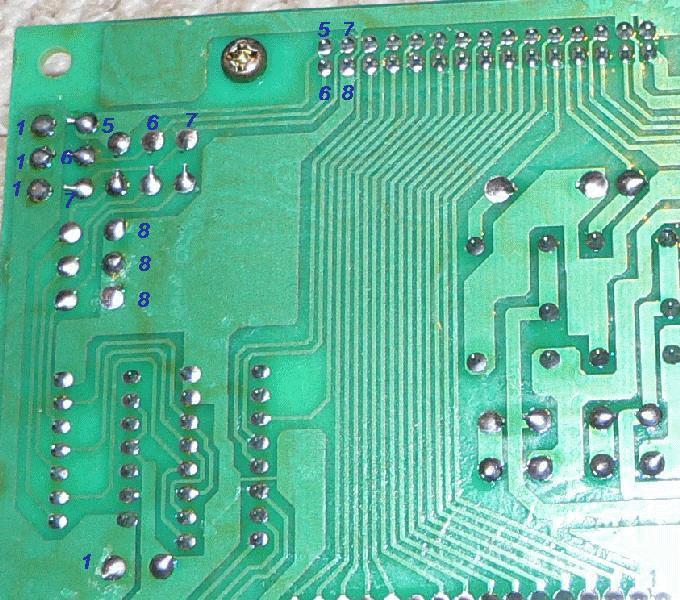
I prefer soldering to the back of the board.
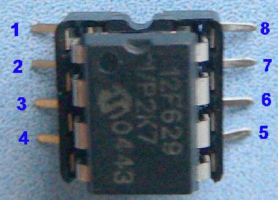
Pin 4 on the Microcontroller wires to the spin lever on your Pachislo. It connects to the wire that changes voltage level when the spin lever is presses. (Should go from 0V to 5V, or 5V to 0V.) If the voltage on this wire is greater than 5V, DO NOT USE THE DIY!
You should use a voltmeter to find the correct wires.
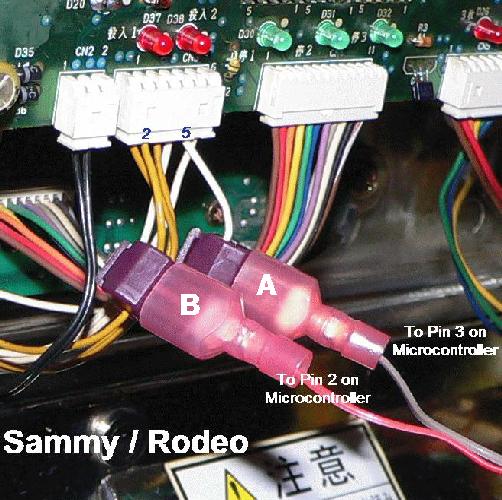
Pins 2 and 3 wire to the coin sensors. (Do not connect if coins sensors are over 5Volts!) See additional information about coin sensor wiring on the PachiTalk page.
Use the following picture to help with connecting the DIY to vintage machines: